|
We can easily program the parallel port in DOS. But as
we know, DOS programs have their own limitations. So, if you want to move
from DOS to Windows, go through this article. This is an introduction to
program the parallel port in VC++. You need not have much knowledge about
VC++. This article is designed for one who know basics of parallel port and
beginners of VC++. If you don't know anything about parallel port, read my
first article "Parallel port programming with C (Part
1)". There you get basic information about parallel port and programming
the port in Turbo C or Borland C.
Now, you are knowing the pins and registers of parallel port. You know how
to access them in DOS. If you want to run your program in Windows 95 or 98,
you are having access to the port in the similar way. You need to know how
to use dialog boxes and windows materials with it. But your program should
also run in Windows XP, NT or higher versions, then there is another issue.
Higher versions of Windows do not allow to access the hardware directly for
security reasons. But still, there are ways, I will explain later. First we
will start programming which will work only in lover versions of Windows.
Direct
Access:
If you want to program the port in VB, there is no direct access to the
port. Still you can access the port using DLL files created with VC++. You
can use the next method Access using inpout32.
If you are familiar with Visual C++, then create a dialog based application
named ParallelPort and skip this section, go to adding
controls.
Creating the
application:
-
Start Visual C++, Select File->New.
-
In the tab 'Projects', Select "MFC
AppWizard (exe)", give project name as "ParallelPort" and click OK.
-
In the next window, select radio
button "Dialog based" and click next leaving all other options
default.
-
Click Finish, then OK to get a
window with two buttons and one sentence "TODO: Place Dialog controls
here.", select and delete that sentence. Click to select the button "Cancel"
and delete it.
-
Right click on button labeled OK,
select Properties from the drop down menu. Change the value of Caption to
"&EXIT" from "OK".
-
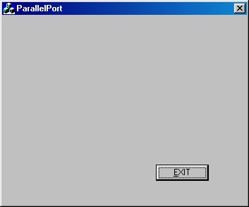
Resize the dialog box to get a window
as shown below. If you run the application by clicking this icon:
 , it should give 0 errors and 0 warnings,
and you will get the following window. , it should give 0 errors and 0 warnings,
and you will get the following window.
 figure(2.1) figure(2.1)
Adding controls:
|
Now, you should see a tool
bar as shown here, it is called Control toolbar. If not, select it from view
menu->toolbars. Icon marked here with red
color is the Check Box. If you click the check box icon and draw in the
window, You will have the check box placed in the window. You need to place
17 such check boxes in the window. You can use copy-past to make your work
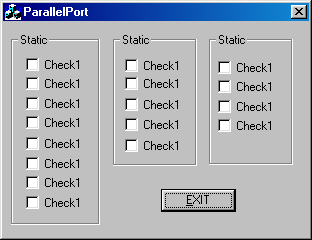
easy. After that, Group then using 3 group boxes. Group box icon is there
above the check box in the figure. After doing this much, your design should
look like figure(2.3). So, re arrange your dialog components to look like
that. Again run the application and make sure that there is no error.
|

figure(2.2) |
 Figure(2.3) Figure(2.3)
Next, right click on the Group Box labeled Static
and go to properties. Change the captions to Data, Status and Control
respectively. Right click on the first Check box Check 1, Change the caption
to "Pin 2" and ID to IDC_Pin2. Similarly change the captions of check boxes
in data group to Pin 2 to Pin 9; status port Pin 10, Pin 11, Pin 12, Pin 13
and Pin 15; Control Port Pin 1, Pin 14, Pin 16 and Pin 17. Change the ID's
correspondingly(IDC_Pin2, IDC_Pin3...).
Window
designing is over. Next part is coding. We have placed some controls in the
dialog box. To get the values of these controls, we need to have variables
associated with then. To do that, right click and select "ClassWizard" from
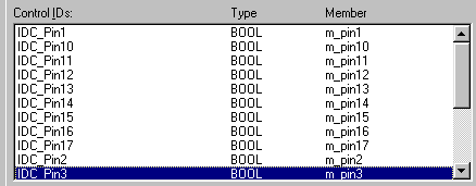
drop down menu. Select tab "Member Variables". You will get a list of
Control IDs. Select each IDs separately and click Add Variable. Type
variable name as m_pin1. m_pin10, m_pin11... and retain Category Value and
Variable type BOOL. Refer following figure.
 Figure(2.4) Figure(2.4)
In
the Workspace, Select ClassView tab, under ParallelPort classes, right click
on CParallelPortDlg, click Add Member Function. Give function type as void
and function name as UpdatePins(). It will take you to the new function
created. Edit the code as follows.
void CParallelPortDlg::UpdatePins()
{
int reg;
reg=_inp(STATUS);
if((reg & 0x40)==0) m_pin10=0;
else m_pin10=1;
if((reg & 0x80)==0) m_pin11=0;
else m_pin11=1;
if((reg & 0x20)==0) m_pin12=0;
else m_pin12=1;
if((reg & 0x10)==0) m_pin13=0;
else m_pin13=1;
if((reg & 0x08)==0) m_pin15=0;
else m_pin15=1;
//////////
reg=_inp(DATA);
if((reg & 0x01)==0) m_pin2=0;
else m_pin2=1;
if((reg & 0x02)==0) m_pin3=0;
else m_pin3=1;
if((reg & 0x04)==0) m_pin4=0;
else m_pin4=1;
if((reg & 0x08)==0) m_pin5=0;
else m_pin5=1;
if((reg & 0x10)==0) m_pin6=0;
else m_pin6=1;
if((reg & 0x20)==0) m_pin7=0;
else m_pin7=2;
if((reg & 0x40)==0) m_pin8=0;
else m_pin8=1;
if((reg & 0x80)==0) m_pin9=0;
else m_pin9=1;
//////
reg = _inp(CONTROL);
if((reg & 0x01)==0) m_pin1=0;
else m_pin1=1;
if((reg & 0x02)==0) m_pin14=0;
else m_pin14=1;
if((reg & 0x04)==0) m_pin16=0;
else m_pin16=1;
if((reg & 0x08)==0) m_pin17=0;
else m_pin17=1;
UpdateData(FALSE);
} |
Now scroll to the top of the page and add these
lines before class declarations.
#define
DATA 0x378
#define STATUS 0x379
#define CONTROL 0x37a |
The function CParallelPortDlg::UpdatePins() is used to display values of all pins initially. Here, we have used _inp()
function to get the values of registers associated with the ports.
_inp(PORT)
will return the data present in PORT. Depending on the status of the pins,
we are making Check boxes checked or unchecked. When we change the value of
member variable and call the function UpdateData(FALSE), the values in the
member variables will be updated in the corresponding controls in the
window. Similarly if you call UpdateData(TRUE), Values which are there in
the corresponding controls will sit in the member variables. Here, The
values from the variables should be updated in the window. So,
UpdateWindow(FALSE). If you have read my first article, you will understand
all other things done here.
To
make run this code when the dialog is initialized, we need to call it. So,
go to function OnInitdialog() in the file CParallelPortDlg. (In the class
view tab of the workspace, under ParallelPort Classes, expand
CParallelPortDlg, you will get the function name, double click it.) Add the
following code to it. This code will call the function UpdatePins() and set
a timer to scan the port pins. You can change the second parameter to change
the frequency at which ports are needed to be scanned. I have used 200 milli
seconds. _outp(CONTROL, 0xDF) will reset the control register bit 5 low so
that data pins will act as output. _outp(PORT,
DATA) sends the byte DATA to the address PORT.
BOOL
CParallelPortDlg::OnInitDialog()
{
//App.Wiz generated code
// TODO: Add extra initialization here
SetTimer(1,200,NULL);
_outp(CONTROL, _inp(CONTROL) & 0xDF);
UpdatePins();
return TRUE;
// return TRUE unless you set the focus to a
control
}
|
Next part is Updating the pin contents for each timer
tics. For that, we need to handle the windows message WM_TIMER. Now since we
have set the timer for 200 ms, for every 200 ms, Windows returns WM_TIMER
message. To write a handler, write click on the CParallelPortDlg in the
class view tab, select "Add Windows Message Handler...". In "New
Windows messages/events", select WM_TIMER and click Add and Edit. It
will take you to the newly created function CParallelPortDlg::OnTimer(UINT
nIDEvent). Add the following code to it.
void
CParallelPortDlg::OnTimer(UINT nIDEvent)
{
// TODO: Add your message handler code
here and/or call default
int status_reg;
status_reg=_inp(STATUS);
if((status_reg & 0x40)==0)
m_pin10=0; else m_pin10=2;
if((status_reg &
0x80)==0) m_pin11=0; else
m_pin11=1;
if((status_reg &
0x20)==0) m_pin12=0; else
m_pin12=1;
if((status_reg & 0x10)==0)
m_pin13=0; else
m_pin13=1;
if((status_reg &
0x08)==0) m_pin15=0; else
m_pin15=1;
UpdateData(FALSE);
CDialog::OnTimer(nIDEvent);
} |
Here, we have refreshed only input pins. Output pins
have to be changed when user clicks on the check boxes. To find any change
of value in check boxes, we can use BN_CLICKED message handler. But for all
the check boxes we have to repeat the process. It is easy to use
ON_COMMAND_RANGE. For that, scroll up to the position in the file
ParallelPortDlg.cpp where you find BEGIN_MESSAGE_MAP(CParallelPortDlg,
CDialog). (Do not confuse between CParallelPortDlg and CAboutDlg.) Add
the following code to it.
BEGIN_MESSAGE_MAP(CParallelPortDlg, CDialog)
//{{AFX_MSG_MAP(CParallelPortDlg)
ON_WM_SYSCOMMAND()
ON_WM_PAINT()
ON_WM_QUERYDRAGICON()
ON_WM_TIMER()
//}}AFX_MSG_MAP
//Code added by me from here.
ON_COMMAND_RANGE(IDC_Pin2, IDC_Pin9, ChangePin)
ON_COMMAND(IDC_Pin14, ChangeControl)
ON_COMMAND(IDC_Pin16, ChangeControl)
ON_COMMAND(IDC_Pin17, ChangeControl)
ON_COMMAND(IDC_Pin1, ChangeControl)
//Code added by me till here
END_MESSAGE_MAP() |
Above code will call the function ChangePin() when buttons
in the range IDC_Pin2 to IDC_Pin9 are changed and ChangeControl() when chack
buttons with ID IDC_Pin14, IDC_Pin16, IDC_Pin17 or IDC_Pin1 are changed. Now
we need those two functions. Add two new functions to CParllelPortDlg: void 'ChangePin()' and 'void ChangeControl()' using the
method explained earlier. Write codes to them as follows:
void
CParallelPortDlg::ChangePin(int pin)
{
int
data_register, new_register;
UpdateData(TRUE);
data_register=_inp( DATA );
new_register=0;
if( m_pin2==TRUE ) new_register |=
0x01;
if( m_pin3==TRUE ) new_register |=
0x02;
if( m_pin4==TRUE ) new_register |=
0x04;
if( m_pin5==TRUE ) new_register |=
0x08;
if( m_pin6==TRUE ) new_register |=
0x10;
if( m_pin7==TRUE ) new_register |=
0x20;
if( m_pin8==TRUE ) new_register |=
0x40;
if( m_pin9==TRUE ) new_register |=
0x80;
_outp(DATA, new_register);
}
void
CParallelPortDlg::ChangeControl()
{
int
control_register, new_register;
UpdateData(TRUE);
control_register = _inp( CONTROL );
new_register = control_register;
if( m_pin1== 0 ) new_register &= 0xFE;
else new_register |=
0x01;
if( m_pin14==0 ) new_register &= 0xFD;
else new_register |=
0x02;
if( m_pin16==0 ) new_register &= 0xFB;
else new_register |=
0x04;
if( m_pin17==0 ) new_register &= 0xF7;
else new_register |=
0x08;
_outp(CONTROL, new_register);
} |
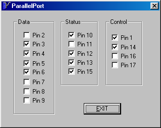
If
everything is OK, you should get the following window when you run the
program. To test the program, run this program without connecting anything
to the port. Change some of the pins and close the window. If you run the
program again you should get the values which was there before closing the
window in the output pins.

You can always use this program to test the parallel
port. Now, make a circuit connecting all the input pins to switches, all the
output pins to LEDs with 2.2K or 10K resisters. If you press switch,
corresponding pin value should change in the screen, If you change state of
any output pin, corresponding LED should glow.
Every
thing is ok. But as you know, this program will run only in win9x. If your
program is needed to run in windows xp and higher versions, you need to
write a kernel mode device driver. Do not worry if you are not up to that
level. There are DLL files available freely for such drivers. You can use
those files and call them from your program.
Access using inpout32
If you do not want
to use driver and test the above program in Windows XP as it is, use my post
in the ElectroSofts Forum
InpOut32 is a DLL file which can send a data to parallel port and which can
return the data in the parallel port. You can download this file with source
code for free from http://logix4u.net. You
can use this file in any windows programming language like Visual
basic, C#, C++ etc. If you know how to use DLL files, download the file from
http://logix4u.net and use Inp32() and
Out32() functions instead of _inp() and _outp().
To
know how to use DLL file in VC++, let us now convert our previous project to
XP enabled program.
-
Add these two lines in the file
ParallelPortDlg.cpp after pre processor directives.
|
short _stdcall
Inp32(short portaddr);
void _stdcall Out32(short portaddr, short
datum);
|
-
Where ever _inp() comes, change them
to Inp32() and where ever outp() comes, change them to Out32().
-
Copy DLL file inpout32.dll and lib
file inpout32.lib got by compiling the source code available at logix4u.net
to the project folder.
-
From project menu, select settings,
go to tab link, in object/ library modules write inpout32.lib
-
Now your program should run without
any errors.
If you have any comment, feedback and
suggestions, please send an e-mail to
[email protected] or
use this feedback form
To discuss the
Interfacing related issues, use Electrosofts Forum
Also Read:
-(next
part)Interfacing example: LCD module
-Programming
the parallel Port(Part 1) with C(DOS)
-Serial Communication via RS232 with C
-Port programming tutorials in
other sites
|