|
You have seen LCD modules used in many of the
electronics devices like coin phone, billing machine and weighing
machines. It is a powerful display options for stand alone systems.
Because of low power dissipation, high readability, flexibility for
programmers; LCD modules are becoming popular. In this article, we will
learn how to connect LCD module to PC parallel port and we will prepare
some library routines for LCD interfacing.
Before starting our study, let us know why you need to
interface LCD or Liquid Crystal Display module to the parallel port .
-
We can easily program the parallel port.
(To know
parallel port programming, we have these two articles in
electroSofts.com:
Parallel Port
Programming (PART 1) : with C, in DOS
Parallel
Port Programming (PART 2): with VC++, in Widows
If you don't know how to program the parallel port, you must
read the first part of the articles mentioned above. So, to study the
LCD module programming, this is easiest method I think.)
-
If you need to modify the code, you need not have to
disconnect the circuit or re-program the chip as you do in the case of
microcontroller.
-
You need to spend less: One LCD module, D25 female
connector, one potentiometer (optional), and some wires- this is what you
need along with a computer.
-
When you are using computer in full screen mode like
Games, movie or TV; You need to exit the application to get a small
updating information from the computer. i.e., if you need to watch time in
that time, you have to close the games. But instead of that you can use
LCD module to display real time from the PC and you can use it along with
your application. Real time implementation from the system clock example
is explained in this article. If you are good in programming, even you can
connect to the internet to get news, stock exchange updates and make them
flash in the LCD module, only if you found it important, you can go
through it by exiting your application.
LCD modules are available in
a wide range like 8x1, 8x2, 16x1, 16x2, 20x2, 20x4, 40x4. Here we have
used 16x2- that means 2 rows of 16 characters. It is a Hitachi
HD44780 compatible module, having 16 pins including 2 pins for backlight.
Following table gives pin structure of LCD
module. LCD modules without backlight will have only 14 pins. If you are
using such LCDs, simply ignore 15th and 16th pins.
|
Pin No |
Symbol |
Details |
|
1 |
GND |
Ground |
|
2 |
Vcc |
Supply Voltage +5V |
|
3 |
Vo |
Contrast adjustment |
|
4 |
RS |
0->Control input, 1-> Data
input |
|
5 |
R/W |
Read/ Write |
|
6 |
E |
Enable |
|
7 to 14 |
D0 to D7 |
Data |
|
15 |
VB1 |
Backlight +5V |
|
16 |
VB0 |
Backlight ground |
To program the LCD module, first we have to initialize
the LCD by sending some control words. RS should be low and E should be
high when we send control. R/W pin 0 mean write data or control to LCD and
R/W pin 1 means read data from the LCD. To send a data to LCD, make RS
high, R/W low, place the data in pins 7 to 14 and make pin E high and low
once. You can understand exact method after seeing the code, later in this
tutorial. To make this let us first build a circuit.
Here, we are going to write on the LCD module and not
reading back. So, R/W is connected to ground directly. We need not have to
input any data through, so all output pins are used in our application.
Data pins of LCD are connected to data pins of the port. Strobe signal
(Pin 1 of D25 connector) is given to E (Pin 6 of LCD), Select printer (Pin
17 of D25) is connected to RS (pin 4 of the LCD).
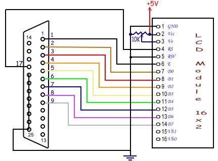
In the above diagram, LCD
module is connected to the lpt port using D25 male connector. Pin number 3
of the LCD is for adjusting the contrast, connected in such a way that it
can be varied from 0V to 5V. Keep it to 0 initially.
If everything is OK, you should
get the LCD module as follows when power is switched ON.
If you get this screen, then
we can start programming. Otherwise check your connections, try by varying
the 10K potentiometer. If you get this display also, you can get maximum
clearness by varying the pot. For me, pot was needed to be nearly 0V. So,
it is OK if you don't use pot also, just connect pin 3 to ground.
Following table explains how
to write control words. When RS=0 and R/W=0, data in the pins D0 to D7
will have following meaning.
| Instruction |
D7 |
D6 |
D5 |
D4 |
D3 |
D2 |
D1 |
D0 |
Description |
| Clear Display |
0 |
0 |
0 |
0 |
0 |
0 |
0 |
1 |
Clears Display
and returns cursor to home position. |
| Cursor home |
0 |
0 |
0 |
0 |
0 |
0 |
1 |
X |
Returns cursor
to home position. Also returns display being shifted to the original
position. |
| Entry mode set |
0 |
0 |
0 |
0 |
0 |
1 |
I/D |
S |
I/D = 0 -->
cursor is in decrement position.
I/D = 1 --> cursor is in increment position.
S = 0 --> Shift is invisible. S = 1 -->
Shift is visible |
| Display ON- OFF
Control |
0 |
0 |
0 |
0 |
1 |
D |
C |
B |
D- Display, C-
cursor, B- Blinking cursor
= 0 --> OFF
=1 --> ON |
| Cursor/ Display
Shift |
0 |
0 |
0 |
1 |
S/C |
R/L |
X |
X |
S/C = 0 --> Move
cursor. S/C = 1 --> Shift display.
R/L = 0 --> Shift left. R/L = 1 --> Shift
right |
| Function Set |
0 |
0 |
1 |
DL |
N |
F |
X |
X |
DL = 0 --> 4 bit
interface. DL = 1 --> 8 bit interface. N = 0 --> 1/8 or 1/11 Duty (1
line). N = 1 --> 1/16 Duty (2 lines). F = 0 --> 5x7 dots.
F = 1 --> 5x10 dots. |
I have left other instruction
related to read and write LCD RAM area, we will see them later. Using
these information, we will write some routines for basic functions of LCD.
Now look at our first program below. Here I have written functions for all
our needs in LCD interfacing. So, in our next programs, we are going to
change our "main" function only. You can save these function as
library and include in your next programs if you want.
#include <dos.h>
#include <string.h>
#include <conio.h>
#include <time.h>
#define PORTADDRESS 0x378 /* Enter Your Port Address Here */
#define DATA PORTADDRESS+0
#define STATUS PORTADDRESS+1
#define CONTROL PORTADDRESS+2
void lcd_init(void);
void lcd_write(char
char2write);
void lcd_putch(char
char2write);
void lcd_puts(char
* str2write);
void lcd_goto(int
row, int column);
void lcd_clear(void);
void lcd_home(void);
void lcd_cursor(int
cursor);
void lcd_entry_mode(int
mode);
void main(void)
{
lcd_init();
lcd_goto(1,1);
lcd_puts("Welcome To");
lcd_goto(1,0);
lcd_puts("electroSofts.com");
while(!kbhit() )
//wait until a key is pressed...
{}
}
void lcd_init()
{
outportb(CONTROL, inportb(CONTROL) &
0xDF);
//config data pins as output
outportb(CONTROL, inportb(CONTROL) | 0x08);
//RS is made high: control (register select)
lcd_write(0x0f);
delay(20);
lcd_write( 0x01);
delay(20);
lcd_write( 0x38);
delay(20);
}
void lcd_write(char
char2write)
{
outportb(DATA, char2write);
outportb(CONTROL,inportb(CONTROL) | 0x01);
/* Set Strobe */
delay(2);
outportb(CONTROL,inportb(CONTROL) & 0xFE);
/* Reset Strobe */
delay(2);
}
void lcd_putch(char
char2write)
{
outportb(CONTROL, inportb(CONTROL) &
0xF7);
//RS=low: data
lcd_write(char2write);
}
void lcd_puts(char
*str2write)
{
outportb(CONTROL, inportb(CONTROL) &
0xF7);
//RS=low: data
while(*str2write)
lcd_write(*(str2write++));
}
void lcd_goto(int
row, int column)
{
outportb(CONTROL, inportb(CONTROL) |
0x08);
if(row==2) column+=0x40;
/* Add these if you are using LCD module
with 4 columns
if(row==2) column+=0x14;
if(row==3) column+=0x54;
*/
lcd_write(0x80 | column);
}
void lcd_clear()
{
outportb(CONTROL, inportb(CONTROL) |
0x08);
lcd_write(0x01);
}
void lcd_home()
{
outportb(CONTROL, inportb(CONTROL) |
0x08);
lcd_write(0x02);
}
void lcd_entry_mode(int
mode)
{
/*
if you dont call this function, entry mode sets to 2 by default.
mode: 0 - cursor left shift, no text shift
1 - no cursor shift, text right shift
2 - cursor right shift, no text shift
3 - no cursor shift, text left shift
*/
outportb(CONTROL, inportb(CONTROL) | 0x08);
lcd_write(0x04 + (mode%4));
}
void lcd_cursor(int
cursor)
{
/*
set cursor: 0 - no cursor, no blink
1 - only blink, no cursor
2 - only cursor, no blink
3 - both cursor and blink
*/
outportb( CONTROL, inportb(CONTROL) | 0x08 );
lcd_write( 0x0c + (cursor%4));
} |
Output of this program should be
like this:

I need not give details to
all the functions above. You can understand them yourself. So, try using
all the functions. In the next examples, we will generate a program that
displays the system time in the LCD module. It may not be having much use
in DOS, but if you transfer the same to Windows, you will gain many
benefits. Also, if your computer will be working in DOS most of the time,
you can think of writing an TSR for the same.
Program to display date and
time in an LCD module: Just replace the 'main' of previous program with
the following and run.
void main(void)
{
struct time
t;
struct date d;
char strtime[17];
textbackground(0);
clrscr();
textcolor(0);
textbackground(10);
gotoxy(8,5);
cputs(" ");
gotoxy(8,4);
cputs(" ");
lcd_init();
lcd_cursor(0);
while(!kbhit())
{
gettime(&t);
getdate(&d);
lcd_goto(0,4);
sprintf(strtime,"%02d:%02d:%02d", t.ti_hour%12, t.ti_min,
t.ti_sec);
lcd_puts(strtime);
gotoxy(12,4);
cputs(strtime);
lcd_goto(1,3);
sprintf(strtime,"%02d:%02d:%4d", d.da_day, d.da_mon, d.da_year);
lcd_puts(strtime);
gotoxy(11,5);
cputs(strtime);
delay(200);
}
textbackground(0);
textcolor(7);
} |
I will stop this article here
itself. You can change these program if you want to interface LCD with
microcontroller. We have many other interesting articles on port
programming in www.electrosofts.com
and other websites.
Click here
get a list of interfacing related articles.
Use Interfacing
section of electrosofts Forum for your comments and doubts. I am
getting many emails and I may not be able to answer all of them.
|