|
What is VHDL?
VHDL stands for very high-speed integrated circuit hardware
description language. Which is one of the programming language used to
model a digital system by dataflow, behavioral and structural style of
modeling. This language was first introduced in 1981 for the department of
Defense (DoD) under the VHSIC programe. In 1983 IBM, Texas instruments and
Intermetrics started to develop this language. In 1985 VHDL 7.2 version
was released. In 1987 IEEE standardized the language.
Describing a design:
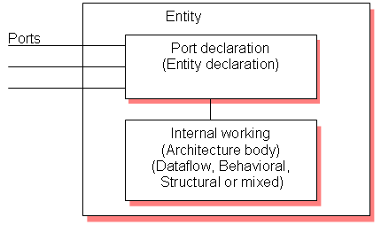
In VHDL an entity is used to describe a hardware module.
An
entity can be described using,
1. Entity declaration.
2. Architecture.
3. Configuration
4. Package declaration.
5. Package body.
Let�s
see what are these?
Entity declaration:
It
defines the names, input output signals and modes of a hardware module.
Syntax:
entity
entity_name is
Port declaration;
end entity_name;
An entity declaration should starts with �entity� and ends with �end�
keywords.
Ports are interfaces through which an entity can communicate with its
environment. Each port must have a name, direction and a type. An entity
may have no port declaration also. The direction will be input, output or
inout.
|
In |
Port can be read |
|
Out |
Port can be written |
|
Inout |
Port can be read and written |
|
Buffer |
Port can be read and written, it
can have only one source. |
Architecture:
It
describes the internal description of design or it tells what is there
inside design. Each entity has atleast one architecture and an entity can
have many architecture. Architecture can be described using structural,
dataflow, behavioral or mixed style. Architecture can be used to describe
a design at different levels of abstraction like gate level, register
transfer level (RTL) or behavior level.
Syntax:
architecture architecture_name of entity_name
architecture_declarative_part;
begin
Statements;
end architecture_name;
Here we should specify the entity name for which we are writing the
architecture body. The architecture statements should be inside the begin
and end keyword. Architecture declarative part may contain variables,
constants, or component declaration.
Configuration:
If an entity contains many architectures and any one of the
possible architecture binding with its entity is done using configuration. It is
used to bind the architecture body to its entity and a component with an
entity.
Syntax:
    configuration configuration_name of entity_name is
       block_configuration;
    end  configuration_name.
Block_configuration defines the binding of components in a block. This can
be written as
    for block_name
       component_binding;
    end for;
block_name is the name of the architecture body. Component binding binds
the components of the block to entities. This can be written as,
    for component_labels:component_name
       block_configuration;
    end for;
Package declaration:
Package declaration is used to declare components, types, constants,
functions and so on.
Syntax:
package package_name is
Declarations;
end package_name;
Package body:
A
package body is used to declare the definitions and procedures that are
declared in corresponding package. Values can be assigned to constants
declared in package in package body.
Syntax:
package body package_name is
Function_procedure definitions;
end package_name;
The
internal working of an entity can be defined using different modeling
styles inside architcture body. They are
1.
Dataflow modeling.
2.
Behavioral modeling.
3.
Structural modeling.
Structure of an entity:

Let�s
try to understand with the help of one example.
Dataflow modeling:
In
this style of modeling, the internal working of an entity can be
implemented using concurrent signal assignment.
Let�s
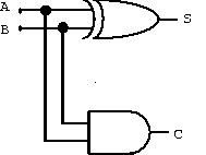
take half adder example which is having one XOR gate and a AND gate.

Library IEEE;
use IEEE.STD_LOGIC_1164.all;

entity ha_en is
            port (A,B:in bit;S,C:out bit);
end ha_en;

architecture ha_ar of ha_en is
begin
            S<=A xor B;
            C<=A and B;

end ha_ar;
|
Here
STD_LOGIC_1164 is an IEEE standard which defines a nine-value logic type,
called STD_ULOGIC. use is a keyword, which imports all the declarations
from this package. The architecture body consists of concurrent signal
assignments, which describes the functionality of the design. Whenever
there is a change in RHS, the expression is evaluated and the value is
assigned to LHS.
Behavioral modeling:
In
this style of modeling, the internal working of an entity can be
implemented using set of statements.
It
contains:
Process
statement is the primary mechanism used to model the behavior of an
entity. It contains sequential statements, variable assignment (:=)
statements or signal assignment (<=) statements etc. It may or may not
contain sensitivity list. If there is an event occurs on any of the
signals in the sensitivity list, the statements within the process is
executed.
Inside
the process the execution of statements will be sequential and if one
entity is having two processes the execution of these processes will be
concurrent. At the end it waits for another event to occur.
library IEEE;
use IEEE.STD_LOGIC_1164.all;

entity ha_beha_en is
      port(
           A : in BIT;
           B : in BIT;
           S : out BIT;
           C : out BIT
           );
end ha_beha_en;


architecture ha_beha_ar of ha_beha_en is
begin
      process_beh:process(A,B)
      begin
          S<= A xor B;
          C<=A and B;
      end process process_beh;

end ha_beha_ar;
|
Here
whenever there is a change in the value of a or b the process statements
are executed.
Structural modeling:
The
implementation of an entity is done through set of interconnected
components.
It
contains:
-
Signal declaration.
-
Component instances
-
Port maps.
-
Wait statements.
Component declaration:
Syntax:
      component component_name [is]
        List_of_interface ports;
     end component component_name;
Before
instantiating the component it should be declared using component
declaration as shown above. Component declaration declares the name of the
entity and interface of a component.
Let�s
try to understand this by taking the example of full adder using 2 half
adder and 1 OR gate.

library IEEE;

use IEEE.STD_LOGIC_1164.all;
entity fa_en is
    port(A,B,Cin:in bit; SUM, CARRY:out bit);
end fa_en;


architecture fa_ar of fa_en is

component ha_en
    port(A,B:in bit;S,C:out bit);

end component;


signal C1,C2,S1:bit;

begin

    HA1:ha_en port map(A,B,S1,C1);
    HA2:ha_en port map(S1,Cin,SUM,C2);
    CARRY <= C1 or C2;

end fa_ar;
|
The
program we have written for half adder in dataflow modeling is
instantiated as shown above. ha_en is the name of the entity in dataflow
modeling. C1, C2, S1 are the signals used for internal connections of the
component which are declared using the keyword signal. Port map is used to
connect different components as well as connect components to ports of the
entity.
Component instantiation is done as follows.
Component_label: component_name port map (signal_list);
Signal_list is the architecture signals which we are connecting to
component ports. This can be done in different ways. What we declared
above is positional binding. One more type is the named binding. The
above can be written as,
HA1:ha_en port map(A => A,B => B, S => S1 ,C => C1 );
HA2:ha_en port map(A => S1,B => Cin, S=> SUM, C => C2);
Test
bench:
The
correctness of the above program can be checked by writing the test bench.
The test
bench is used for generating stimulus for the entity under test. Let�s
write a simple test bench for full adder.
library IEEE;

use IEEE.STD_LOGIC_1164.all;

entity tb_en is

end tb_en;

architecture tb_ar of tb_en is
signal a_i,b_i,c_i,sum_i,carry_i:bit;

begin

   eut: entity work.fa_en(fa_ar)
        port map(A=>a_i,B=>b_i,Cin=>c_i,SUM=>sum_i,CARRY=>carry_i);

stimulus: process
              begin
                  a_i<='1';b_i<='1';c_i<='1';
                  wait for 10ns;
                  a_i<='0';b_i<='1';c_i<='1';
                  wait for 10ns;
                  a_i<='1';b_i<='0';c_i<='0';
                  wait for 10ns;
                  if now=30ns then
                      wait;
                  end if;

end process stimulus;

end tb_ar;
|
Here now
is a predefined function that returns the current simulation time
What we saw upto this is component instantiation by positional and by
name. In this test bench example the entity is directly instantiated. The
direct entity instantiation syntax is:
Component_label: entity entity_name (architecture_name)
port map(signal_list);
|