|
The key board here we are interfacing is a matrix
keyboard. This key board is designed with a particular rows and columns.
These rows and columns are connected to the microcontroller through its
ports of the micro controller 8051. We normally use 8*8 matrix key board.
So only two ports of 8051 can be easily connected to the rows and columns
of the key board.
When ever a key is pressed, a row and a column gets shorted through that
pressed key and all the other keys are left open. When a key is pressed
only a bit in the port goes high. Which indicates microcontroller that
the key is pressed. By this high on the bit key in the corresponding
column is identified.
Once we are sure that one of key in the key board is pressed next our aim
is to identify that key. To do this we firstly check for particular row
and then we check the corresponding column the key board.
To check the row of the pressed key in the keyboard, one of the row is
made high by making one of bit in the output port of 8051 high . This is
done until the row is found out. Once we get the row next out job is to
find out the column of the pressed key. The column is detected by
contents in the input ports with the help of a counter. The content of the
input port is rotated with carry until the carry bit is set.
The contents of the counter is then compared and displayed in the
display. This display is designed using a seven segment display and a BCD
to seven segment decoder IC 7447.
The BCD equivalent number of counter is sent through output part of 8051
displays the number of pressed key.

Circuit
diagram of
INTERFACING KEY BOARD TO 8051.
The
programming algorithm, program and the circuit diagram is as follows. Here
program is explained with comments.
Circuit diagram of
INTERFACING KEY BOARD TO 8051.
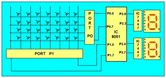
Keyboard is
organized in a matrix of rows and columns as shown in the figure. The
microcontroller accesses both rows and columns through the port.
-
The 8051 has 4 I/O ports P0 to P3
each with 8 I/O pins, P0.0 to P0.7,P1.0 to P1.7, P2.0 to P2.7, P3.0 to
P3.7. The one of the port P1 (it understood that P1 means P1.0 to P1.7)
as an I/P port for microcontroller 8051, port P0 as an O/P port of
microcontroller 8051 and port P2 is used for displaying the number of
pressed key.
-
Make all rows of port P0
high so that it gives high signal when key is pressed.
-
See if any key is pressed
by scanning the port P1 by checking all columns for non zero condition.
-
If any key is pressed, to
identify which key is pressed make one row high at a time.
-
Initiate a counter to hold
the count so that each key is counted.
-
Check port P1 for nonzero
condition. If any nonzero number is there in [accumulator], start column
scanning by following step 9.
-
Otherwise make next row
high in port P1.
-
Add a count of 08h to the
counter to move to the next row by repeating steps from step 6.
-
If any key pressed is
found, the [accumulator] content is rotated right through the carry
until carry bit sets, while doing this increment the count in the
counter till carry is found.
-
Move the content in the counter to
display in data field or to memory location
-
To
repeat the procedures go to step 2.
Program to interface matrix
keyboard to microcontroller 8051
|
Start of main program:
to check that whether
any key is pressed
start:
mov a,#00h
mov p1,a ;making all
rows of port p1 zero
mov a,#0fh
mov p1,a ;making all
rows of port p1 high
press:
mov a,p2
jz press
;check until any key is pressed
after making sure that any key is
pressed
mov a,#01h ;make one row
high at a time
mov r4,a
mov r3,#00h ;initiating
counter
next:
mov a,r4
mov p1,a ;making one
row high at a time
mov a,p2 ;taking input
from port A
jnz
colscan ;after getting the row jump to check
column
mov a,r4
rl a ;rotate
left to check next row
mov r4,a
mov a,r3
add a,#08h ;increment
counter by 08 count
mov r3,a
sjmp next
;jump to check next row
after identifying the row
to check the colomn following
steps are followed
colscan: mov
r5,#00h
in:
rrc a ;rotate right with carry until get the carry
jc out
;jump on getting carry
inc r3 ;increment one
count
jmp in
out:
mov a,r3
da a ;decimal
adjust the contents of counter
before
display
mov p2,a
jmp start ;repeat
for check next key. |
|