|
Example I
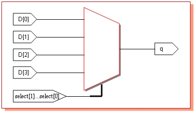
If select is 0, output q will be d[0]; if select is 1, q will be d[1]; if
select is 2, q will be d[2] and if select is 3, q will be d[3]. This logic
can be implemented using Verilog code as follows:
declaration 'input[1:0]
select;' specifies
select as port of 2 bits, with MSB select[1] and LSB select[0]. All the ports
are declared as arrays because all the input signals must be declared as wires
and left side of continuous statements should be wire. Actually, ports are
wire by default and we need not declare it. But it is better to declare for
our convenience.
When select is 00, q will be assigned d[0], when select is 01, q will be assigned
d[1] and so on. To test this, use following testbench. It generates a truth
table with all possible values in the input and select.
// Verilog testbench for 4 to 1 Multiplexer
// by Harsha Perla for http://electrosofts.com
// Comments to: [email protected]
// Available at http://electrosofts.com/verilog

module mux_tb;

reg[3:0] d;
reg[1:0] select;
wire     q;

integer  i;

mux1 my_mux( select, d, q );

initial
begin
   #1 $monitor("d = %b", d, "  |  select = ", select, "  |  q = ", q );

   for( i = 0; i <= 15; i = i + 1)
   begin
      d = i;
      select = 0;  #1;
      select = 1;  #1;
      select = 2;  #1;
      select = 3;  #1;
      $display("-----------------------------------------");
    end

end
endmodule
|
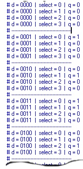 $monitor
keeps displaying the values of its arguments whenever one of that changes.
i.e., whenever values of d, select or q changes, it displays the value in
the output window. Using a for loop, I have changed value of d from 0000 to
1111, and in each case change the value of select to all possible values.
A part of output is as displayed the diagram in the right.
$monitor
keeps displaying the values of its arguments whenever one of that changes.
i.e., whenever values of d, select or q changes, it displays the value in
the output window. Using a for loop, I have changed value of d from 0000 to
1111, and in each case change the value of select to all possible values.
A part of output is as displayed the diagram in the right.
Note that if we use
for(
d = 0;
d <= 15;
d = d +
1)
instead of
for(
i = 0;
i <= 15;
i = i +
1),
for loop will go to infinite loop since d can never
be greater that 15; so the condition d <= 15 will always be true.
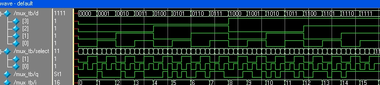
Wave output of the above code taken from the
ModelSim simulation is shown bellow.
You can use same test bench for all the multiplexer codes here. This
output and wave diagrams are same for all the codes.
Example II
This example is very similar to previous one, but instead of using continuous
assignments, here always
statement is used. left side of expressions inside an always block must be
of register type. So, here q is declared s reg. When ever d or select
changes, q should be changed to d[select]. So, d and select are added
to the 'sensitivity list'. Even though we declared q is reg here, hardware
register won't be used by synthesis tool to implement q. This is because always
block here is combinational. Remember that if sensitivity list contains right
hand side signals in the expressions and blocking statements are used, it
will be combinational circuit when synthesising.
Use the same testbench as previous one for this code. Change
mux1 my_mux
by mux2 my_mux.
Example III
This example uses if statement of Verilog. Here
also q is declared as reg and other signals as wire. This example also
uses always block with the same sensitivity list. You can understand this
code very easily.
// Verilog code for Multiplexer implementation using if statement.
// by Harsha Perla for http://electrosofts.com
// [email protected]
// Available at http://electrosofts.com/verilog

module mux3( select, d, q );

input[1:0] select;
input[3:0] d;
output q;

reg q;
wire[1:0] select;
wire[3:0] d;

always @( select or d )
begin
   if( select == 0)
      q = d[0];

   if( select == 1)
      q = d[1];

   if( select == 2)
      q = d[2];

   if( select == 3)
      q = d[3];
end

endmodule
|
Actually this example (next one also) has more code to write. But if
select and input signals are having separate name instead of packed arrays
like d1, d2, select1. This code is more easy to understand and very useful
if inputs are coming from different sources.
Example IV
Next example is also similar one. Here, case statement is used. case
statement switches the execution of the code to corresponding block
depending on the value of the parameter passed.
// Verilog code for Multiplexer implementation using case statement.
// by Harsha Perla for http://electrosofts.com
// [email protected]
// Available at http://electrosofts.com/verilog

module mux4( select, d, q );

input[1:0] select;
input[3:0] d;
output     q;

reg       q;
wire[1:0] select;
wire[3:0] d;

always @( select or d )
begin
   case( select )
       0 : q = d[0];
       1 : q = d[1];
       2 : q = d[2];
       3 : q = d[3];
   endcase
end

endmodule
|
Example V
This example uses nested conditional statement. Meaning of the assign
statement in the following code is "If select = 0, q = d[0], else if
select is 1 q = d[1]. else if select is 2 q = d[2], else q = d[3]. We can
use conditional statement inside always block also.
// Verilog code for Multiplexer implementation using conditional statement.
// by Harsha Perla for http://electrosofts.com
// [email protected]
// Available at http://electrosofts.com/verilog

module mux5( select, d, q );

input[1:0] select;
input[3:0] d;
output q;

wire q;
wire[1:0] select;
wire[3:0] d;

assign q = ( select == 0 )? d[0] : ( select == 1 )? d[1] : ( select == 2 )? d[2] : d[3];

endmodule
|
All the examples till now uses behavioral style of coding. Next example is
data flow style of code.
Example VI
If we write an expression for 4 to 1 multiplexer, we can convert the
expression in to code. Consider the expression bellow:
q = (
select[0].select[1].d[0]
) + ( select[0].select[1].d[1]
) + ( select[0].select[1].d[2]
) + ( select[0].select[1].d[3] )
You can write a truth table to verify the equation. Now we can write a
code using Verilog for this equation as follows. We can also use assign
statement instead of writing always block.
// Verilog code for Multiplexer implementation in dataflow level.
// by Harsha Perla for http://electrosofts.com
// [email protected]
// Available at http://electrosofts.com/verilog

module mux6( select, d, q );

input[1:0] select;
input[3:0] d;
output q;

reg q;
wire[1:0] select;
wire[3:0] d;

always @( select or d)
begin
    q =       ( ~select[0] & ~select[1] & d[0] )
            | (  select[0] & ~select[1] & d[1] )
            | ( ~select[0] &  select[1] & d[2] )
            | (  select[0] &  select[1] & d[3] );
end

endmodule
|
Example VII
This example is gate level implementation of the
multiplexer. All basic gates are declared in Verilog. We can instantiate
them to get a gate level circuit. Let us draw the diagram of multiplexer
first.
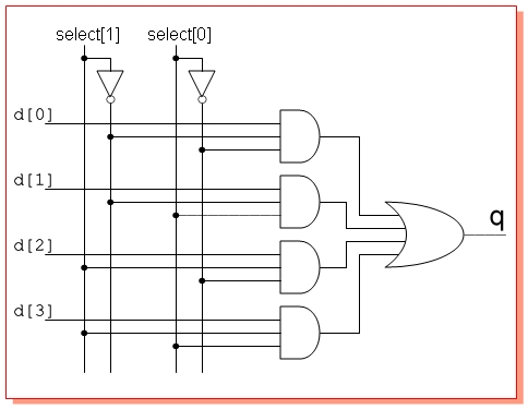
Now, convert the circuit in to code. instantiate
2 NOT gates, four AND gates and one OR gate as in the diagram. All the
outputs from the gates should be wire. Hence code contains all the signals
as wires.
// Verilog code for Mux implementation using instantiating gates.
// by Harsha Perla for http://electrosofts.com
// [email protected]
// Available at http://electrosofts.com/verilog

module mux7( select, d, q );

input[1:0] select;
input[3:0] d;
output     q;

wire       q, q1, q2, q3, q4, NOTselect0, NOTselect1;
wire[1:0]  select;
wire[3:0]  d;

not n1( NOTselect0, select[0] );
not n2( NOTselect1, select[1] );

and a1( q1, NOTselect0, NOTselect1, d[0]  );
and a2( q2,  select[0], NOTselect1, d[1]  );
and a3( q3, NOTselect0,  select[1], d[2]  );
and a4( q4,  select[0],  select[1], d[3]  );

or o1( q, q1, q2, q3, q4 );

endmodule
|
Click here to to
download all the examples
More tutorials on Verilog is to be added soon.
Verilog: Table of
Contents
|