|
Designing a
synchronous finite state machine (FSM) is a common task for a digital logic
engineer. A finite state machine can be divided in to two types: Moore and
Mealy state machines. Fig. 1 has the general structure for Moore and Fig. 2
has general structure for Mealy. The current state of the machine is stored
in the state memory, a set of n flip-flops clocked by a single clock signal
(hence �synchronous� state machine). The state vector (also current state,
or just state) is the value currently stored by the state memory. The next
state of the machine is a function of the state vector in Moore; function of
state vector and the inputs in Mealy.
Fig. 1: Moore State Machine
Fig. 2: Mealy State Machine
Verilog
Coding
The logic in a state machine is described using a case
statement or the equivalent (e.g., if-else). All possible combinations of
current state and inputs are enumerated, and the appropriate values are
specified for next state and the outputs. A state machine may be coded as in
Code 1 using two separate case statements, or, as in code 2, using only one.
A single case statement may be preferred for Mealy machines where the
outputs depend on the state transition rather than just the current state.
Consider the
case of a circuit to detect a pair of 1's or 0's in the single bit input.
That is, input will be a series of one's and zero's. If two one's or two
zero's comes one after another, output should go high. Otherwise output
should be low.
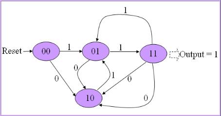
Here is a
Moore type state transition diagram for the circuit. When reset, state goes to 00;
If input is 1, state will be 01 and if input is 0, state goes to 10. State
will be 11 if input repeats. After state 11, goes to 10 state or 01
depending on the inp, since
overlapping pair should not be considered. That is, if 111 comes, it should
consider only one pair.
Following code the Verilog
implementation of the state machine. Note that we updated outp and state in
separate always blocks, it will be easy to design. inp is serial input, outp
is serial output, clk is clock and rst is asynchronous reset. I have used
nonblocking statements for assignments because we use previous state to
decide the next state, so state should be registered.
module fsm( clk, rst, inp, outp);

   input clk, rst, inp;
   output outp;

   reg [1:0] state;
   reg outp;

   always @( posedge clk, posedge rst )
   begin
   if( rst )
       state <= 2'b00;
   else
   begin
       case( state )
       2'b00:
       begin
            if( inp ) state <= 2'b01;
            else state <= 2'b10;
       end

       2'b01:
       begin
            if( inp ) state <= 2'b11;
            else state <= 2'b10;
       end

       2'b10:
       begin
            if( inp ) state <= 2'b01;
            else state <= 2'b11;
       end

       2'b11:
       begin
            if( inp ) state <= 2'b01;
            else state <= 2'b10;
       end
       endcase
   end
end


always @(posedge clk, posedge rst)
begin
    if( rst )
       outp <= 0;
    else if( state == 2'b11 )
       outp <= 1;
    else outp <= 0;

end

endmodule
|
Here is a testbench that can be used
to test all these examples. This testbench generates both directed and
random test values. We can specify the sequence in the first part.
module fsm_test;

reg  clk, rst, inp;
wire outp;
reg[15:0] sequence;
integer i;

fsm dut( clk, rst, inp, outp);

initial
begin

   clk = 0;
        rst = 1;
        sequence = 16'b0101_0111_0111_0010;
   #5 rst = 0;

   for( i = 0; i <= 15; i = i + 1)
   begin];
      #2 clk = 1;
      #2 clk = 0;
      $display("State = ", dut.state, " Input = ", inp, ", Output = ", outp);

   end
        test2;
end
task test2;
   for( i = 0; i <= 15; i = i + 1)
   begin
      inp = $random % 2;
      #2 clk = 1;
      #2 clk = 0;
      $display("State = ", dut.state, " Input = ", inp, ", Output = ", outp);

   end
endtask


endmodule
|
Now, let us re-design the above
circuit using Mealy style state machine. Output depends on both state and
input. State transition diagram is as follows:
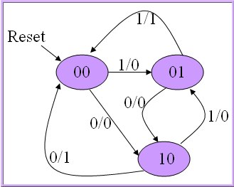
When reset, state becomes idle, that
is 00. Next, if 1 comes, state becomes 01 and if 0 comes state becomes 10
with output 0. We have showed input 1, output 0 as 1/0. If input bit
repeats, output becomes 1 and state goes to 00.
I implemented this state machine as in
the code bellow. Only one always block is used because both outp and state
are dependent on state and inp.
module mealy( clk, rst, inp, outp);

   input clk, rst, inp;
   output outp;

   reg [1:0] state;
   reg outp;

   always @( posedge clk, posedge rst ) begin
   if( rst ) begin
       state <= 2'b00;
       outp <= 0;
   end
   else  begin
       case( state )
       2'b00: begin
            if( inp ) begin
               state <= 2'b01;
               outp  <= 0;
            end
            else begin
                state <= 2'b10;
                outp <= 0;
            end
       end

       2'b01: begin
            if( inp ) begin
                state <= 2'b00;
                outp  <= 1;
            end
            else  begin
               state <= 2'b10;
               outp <= 0;
            end

       end

       2'b10: begin
            if( inp ) begin
                state <= 2'b01;
                outp  <= 0;
            end
            else begin
               state <= 2'b00;
               outp <= 1;
            end

       end

       default: begin
            state <= 2'b00;
            outp <= 0;
       end
     endcase
   end
end

endmodule
|
Now, let us discuss difference between
Moore and Mealy state machines depending on these codes.
-
Moore state
machine is easier to design than Mealy. First design the states depending on
the previous state and input. Then design output only depending on state.
Whereas in Mealy, you have to consider both state and input while designing
the output.
-
Mealy state
machine uses less states than the Moore. Since inputs influence the output
in the immediate clock, memory needed to remember the input is less. So, it
uses less flip flops and hence circuit is simpler.
-
In Mealy,
output changes immediately when the input changes. We can observe this point
when you simulate the codes above. In Moore example, output becomes high in
the clock next to the clock in which state goes 11. So, Mealy is faster than
Moore. Mealy gives immediate response to input and Moore gives response in
the next clock.
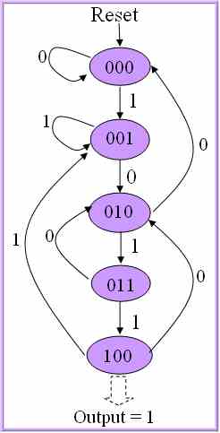
Sequence detector:
Let us
design a circuit to detect a sequence of 1011 in serial input. This is an
overlapping sequence. So, if 1011011 comes, sequence is repeated twice.
Consider these two circuits. First one is Moore and second one is Mealy. In
Moore design below, output goes high only if state is 100. Note that we have
used 1 less state than Mealy and hence one flip flop less will be enough to
design state machine.
 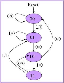
This time I will try to
implement only Mealy machine. Try to understand the state diagram and
compare them first.
When reset,
state goes to 00, where there is no previous inputs. State remains same
until we get a '1' in the input since there is no possibility of start of
sequence. If a 1 comes in the input, it may be start of sequence, so go to
state 01. From 01, if again 1 comes, that means sequence is broken. But
there is a possibility of start of another new sequence. So, 01 is start of
sequence and stay in the same state. If zero comes, go to state 10.
Another 0
when state is 10 breaks the sequence and state goes to 00, no sequence. If 1
comes, continue to next state 11.
If again 1
comes, sequence completes. Make the output high and go to state 01, because
there may be a overlapping sequence as I mentioned earlier. If zero comes,
sequence breaks and state goes to 10 since it may be second bit of another
sequence.
module m1011( clk, rst, inp, outp);

   input clk, rst, inp;
   output outp;

   reg [1:0] state;
   reg outp;

   always @( posedge clk, rst )
   begin
   if( rst )
       state <= 2'b00;
   else
   begin
       case( {state,inp} )
          3'b000: begin
             state <= 2'b00;
             outp  <= 0;
          end
          3'b001: begin
             state <= 2'b01;
             outp  <= 0;
          end
          3'b010: begin
             state <= 2'b10;
             outp  <= 0;
          end
          3'b011: begin
             state <= 2'b01;
             outp  <= 0;
          end
          3'b100: begin
             state <=<= 0;
          end
          3'b101: begin
             state <= 2'b11;
             outp  <= 0;
          end
          3'b110: begin
             state <= 2'b10;
             outp  <= 0;
          end
          3'b111: begin
             state <= 2'b01;
             outp  <= 1;
          end

       endcase
   end
end

endmodule
|
This time I
combined state and inp using concatenation operator {} to make code smaller.
state and inp is used together to select the case. Using this a I avoided
if-begin-end-else-begin-end in every case. |