|
< Previous: ( Scrambling and
descrambling )
Table of Contents
Next: ( Under Construction ) >
I already said in one of the
previous sections that the STS SPE would be floating and the pointers give
the position from where it is going to start. The phase differences
between Transport Overhead and SPE must be accommodated. Also SONET/SDH
systems are synchronous systems, i.e., all the clocks are supposed to be
same, but in reality they are not. There shall always be small
differences. Even when all the clocks are same there can be jitter, which
must also be accommodated. Data can come into a device slower or faster
than it is transmitted out at the other side. So something has to be done
to adjust the differences between the transmit and receive clocks. This is
where pointer action bytes H1, H2, and H3 come in.
H1 and H2 bytes are called pointer
bytes. Consider H1 and H2 as shown in figure-6. Bits 1 to 4 are called New
Data Flag (NDF) bits represented by Ns. It is set to 0110 for normal operation. Bits 5 and 6
are currently undefined in SONET but are used in SDH, which we will study
when we go through SDH. Bits 7 to 16 carry the pointer value.
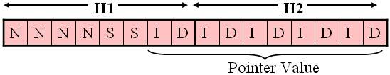
Figure-6
The value of the bits 7 to 16 can
vary from 0 to 782. A value of 0 indicates that SPE starts at the first
byte immediately after H3 byte. If the pointer value is 1 the payload
starts at the second byte after H3 etc. Figure 6 shows the layout of H1
and H2 pointer. For the time being ignore the meaning of �I� and �D�
labels.
Figure 7 below shows locations of
SPE for different values of pointer.
|
1 |
2 |
3 |
4 |
5 |
6 |
|
89 |
90 |
| |
|
|
|
|
|
|
|
|
| |
|
|
|
|
|
|
|
|
| |
|
|
|
|
|
|
|
|
|
H1 |
H2 |
H3 |
0 |
1 |
2 |
|
85 |
86 |
| |
|
|
87 |
88 |
|
|
|
|
| |
|
|
|
|
|
|
|
|
| |
|
|
|
|
|
|
|
|
| |
|
|
|
|
|
|
|
|
| |
|
|
|
|
|
|
|
521 |
| |
|
|
|
|
|
|
|
|
| |
|
|
522 |
523 |
|
|
|
|
| |
|
|
|
|
|
|
|
|
| |
|
|
|
|
|
|
781 |
782 |
|
H1 |
H2 |
H3 |
0 |
1 |
|
|
|
|
| |
|
|
|
|
|
|
|
|
| |
|
|
|
|
|
|
|
|
| |
|
|
|
|
|
|
|
|
| |
|
|
|
|
|
|
|
|
| |
|
|
|
|
|
|
|
|
| |
Negative stuff Opportunity |
| |
Positive stuff opportunity |
Figure 7
Now
let us see why and how H3 is used.
Suppose the incoming clock is
faster than the outgoing clock. Then an extra byte is accumulated in our
receive buffer, compared to what we can transmit. Now this extra byte is
put into H3 location. So when we transmit one SONET frame of 810 bytes, we
actually transmit 784 bytes of payload (86 columns times 9 rows, plus one
H3 octet), rather than 783 bytes of payload.
A similar problem occurs if the
incoming clock is slower than the outgoing clock. Then there will be a
deficit in the receiver buffer. To overcome this problem a stuff byte in
the location after the H3 byte is sent. Moving of SPE backwards is called
negative justification and moving it forward is called positive
justification.
In figure-6 pointer bits are
labeled as IDIDIDIDID. �I� indicates increment and �D� indicates
decrement. With the help of these I and D bits we can make positive or
negative justification. Let us go through how these positive and negative
justifications are done.
Sonet equipment will have a
register using which it compares the present pointer bits with the
previous bits. If �I� bits are inverted then pointer value is incremented
(positive justification) or if �D� bits are inverted then pointer value is
decremented (negative justification). By changing the NDF value also new
pointer value can be introduced. We shall discuss all this in more detail.
Positive Justification:
|
Frame Status |
New Data Flag |
Unused Bits |
I |
D |
I |
D |
I |
D |
I |
D |
I |
D |
|
Normal Frame |
0 |
1 |
1 |
0 |
X
|
X |
0 |
0 |
1 |
1 |
0 |
1 |
0 |
1 |
1 |
0 |
|
Inverted I bits |
0 |
1 |
1 |
0 |
X |
X |
1 |
0 |
0 |
1 |
1 |
1 |
1 |
1 |
0 |
0 |
|
New Ptr Value |
0 |
1 |
1 |
0 |
X |
X |
0 |
0 |
1 |
1 |
0 |
1 |
0 |
1 |
1 |
1 |
|
New Ptr Value |
0 |
1 |
1 |
0 |
X |
X |
0 |
0 |
1 |
1 |
0 |
1 |
0 |
1 |
1 |
1 |
|
Normal Frame |
0 |
1 |
1 |
0 |
X |
X |
0 |
0 |
1 |
1 |
0 |
1 |
0 |
1 |
1 |
1 |
Figure-8
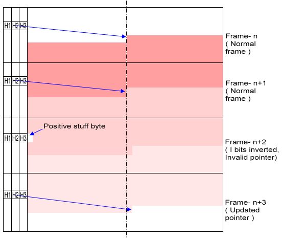
Figure-9
Consider Figures 8 and 9 for the
explanation that follows. Let the pointer value be 214. Its decimal
equivalent is 0011010110 which is shown in first row in figure-8. Now at
the frame where positive justification should be done the I bits are
inverted which is shown in the second row in figure-8. It is in this frame
that the byte after the H3 is stuffed. As soon as the receiver detects
that the I bits are inverted, it discards the byte after H3 as the content
is meaningless-but it usually contains all 0s and also the pointer value
is incremented at the receiver side to point to the adjusted payload.
In the next frame the receiver
receives the incremented pointer value. This new pointer value is repeated
for the next frame as well as for the fourth frame. The new pointer value
received in the fourth frame is available for pointer adjustment again
where as that received in the previous two frames is not available for
adjustment. This is because a new pointer value is accepted only when it
is received for three consecutive frames.
Negative Justification:
|
Frame Status |
New Data Flag |
Unused Bits |
I |
D |
I |
D |
I |
D |
I |
D |
I |
D |
|
Normal Frame |
0 |
1 |
1 |
0 |
X |
X |
0 |
0 |
1 |
1 |
0 |
1 |
0 |
1 |
1 |
0 |
|
Inverted D bits |
0 |
1 |
1 |
0 |
X |
X |
0 |
1 |
1 |
0 |
0 |
0 |
0 |
0 |
1 |
1 |
|
New Ptr Value |
0 |
1 |
1 |
0 |
X |
X |
0 |
0 |
1 |
1 |
0 |
1 |
0 |
1 |
0 |
1 |
|
New Ptr Value |
0 |
1 |
1 |
0 |
X |
X
|
0 |
0 |
1 |
1 |
0 |
1 |
0 |
1 |
0 |
1 |
|
Norm Frame |
0 |
1 |
1 |
0 |
X |
X |
0 |
0 |
1 |
1 |
0 |
1 |
0 |
1 |
0 |
1 |
Figure-10

Figure-11
Consider Figures 10 and 11 for the
explanation that follows. It is very much similar to positive
justification. Let the pointer value be 214. Its decimal equivalent is
shown in first row in figure-8. Now at the frame where negative
justification should be done the �D� bits are inverted which is as shown
in the second row in figure-10. It is in this frame that the byte after
the H3 is used to carry a data byte. As soon as the receiver detects that
the �D� bits are inverted, it immediately takes up H3 as it contains some
relevant data and also the pointer value is decremented at the received
SONET equipment to point to the adjusted payload.
In the next frame the receiver
receives the decremented pointer value. This new pointer value is repeated
for the next frame as well as for the fourth frame. The new pointer value
received in the fourth frame is available for pointer adjustment again.
Pointer Adjustment Using NDF:
|
Frame Status |
New Data Flag |
Unused Bits |
I |
D |
I |
D |
I |
D |
I |
D |
I |
D |
|
Normal Frame |
0 |
1 |
1 |
0 |
X |
X |
0 |
0 |
0 |
1 |
0 |
1 |
0 |
1 |
0 |
1 |
|
NDF Set |
1 |
0 |
0 |
1 |
X |
X |
0 |
0 |
0 |
1 |
0 |
1 |
0 |
1 |
1 |
0 |
|
New Ptr Value |
0 |
1 |
1 |
0 |
X |
X |
0 |
0 |
0 |
1 |
0 |
1 |
0 |
1 |
1 |
0 |
|
New Ptr Value |
0 |
1 |
1 |
0 |
X |
X |
0 |
0 |
0 |
1 |
0 |
1 |
0 |
1 |
1 |
0 |
|
Normal Frame |
0 |
1 |
1 |
0 |
X |
X |
0 |
0 |
0 |
1 |
0 |
1 |
0 |
1 |
1 |
0 |
Figure-12
Till now we have discussed
incrementing or decrementing of pointer value only by 1. What if we want
to adjust pointer value by more than 1. This can be achieved using NDF.
To make adjustments using NDF, it's bits must be set to1001. The frame in
which NDF is set new pointer value is introduced immediately. Here there
is no need for inversion of �I� or �D� bits. Pointer adjustments using NDF
cannot occur more often than every fourth frame in SONET. This is so
because the new pointer value is accepted only if it is received for three
consecutive frames. Another reason for the limit of every fourth SONET
frame is because of two special cases.
Special Cases:
In
the positive pointer adjustment case suppose the pointer is changed from
782 to zero. Here you can see that the pointer in the frame following the
frame with the NDF inverted will point to the same SPE as the (implied)
pointer of the frame with the inverted NDF. This means that the system has
to ignore the pointer for one SONET frame and the first valid pointer will
be the third SONET frame (the frame with the NDF inverted is one, the next
frame is two, and the third frame has a valid pointer).
A
similar special case occurs when the pointer rolls over backwards from
zero to 782. The zero value pointer is pointing at the byte after the H3
byte. The next frame has the NDF set and the H3 byte is used for data. The
resultant pointer is pointing to the H3 byte. The beginning of the next
SPE is the last byte in row 3 of the SONET frame after the frame with the
NDF inverted. However, the pointer in that frame cannot point backwards in
the frame, so the SONET equipment has to handle this situation as a
special case. The pointer in that SONET frame points to the last byte in
row 3 of the next (third) SONET frame. This can be confusing but if you
draw pictures similar to Figure 9 and Figure 11 you shall see how it
works.
We
will be processing pointers in a different way when we are using
concatenated structures, which we will be discussing later.
|