|
Here is a PC based
Game show/ quiz buzzer, which makes a quiz 'priority less'. Instead of allowing only
the first person who presses the buzzer first to answer, this buzzer
introduces a new idea called 'Priority passing'. Uses PC parallel port to
input response from the buzzer.
Introduction:
The attraction of any game show depends on the
visual effects. The way in which they present different rounds makes the
game shows effective. The good Quiz show always contains one or more
buzzer rounds.
The buzzer makes a round of a Quiz show 'fastest finger first '. The
active buzzer makes the team to first respond to the question. A common
question will be asked for all the teams in these rounds. The team which
presses the buzzer first gets first chance to answer. To avoid confusion
of the teams to be answered when one or more team presses the buzzer
almost simultaneously, buzzer circuits are used.
Instead of just showing who pressed the buzzer using
some LED or electric
bulb, if has some visual effects, audio effects and different options that
makes the show entice. So our approach is to make this possible which
includes all the features. This project makes the show attractive and easy
to operate. This Quiz buzzer is built with the view of making the game
show
priority less.
This project uses PC parallel port to input user's response from the
switches placed in the participant's table. Response of the teams can be
projected on to a screen. Number of all the teams will be displayed in the
screen in order of the response.
This project uses Turbo C version 3.0 for programming. If you don't know
the parallel port interfacing, read
http://electrosofts.com/parallel :
Parallel port interfacing
tutorial. If you are using windows xp and other compilers, you may need to
read Parallel
port interfacing: windows. You can use this idea and convert the
project for windows, try it...
Circuit
This project uses parallel port in
normal( unidirectional ) mode. So, we have only 5 input pins available.
Here, we assumed there are 6 teams. So we need extra input pins. This can
be done by multiplexing the signals.
Circuit of the quiz buzzer consists of
the following components:
-
Multiplexer IC 74157
-
10kΩ resistors (6)
-
5volt dc power supply
-
D-25 type connectors
-
Push switches (6)
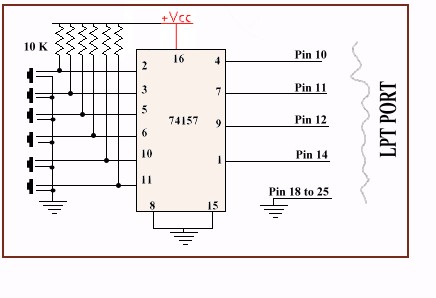
The circuit diagram is as shown
above. the pins 10,11,12,14 of the D-25 connector are connected to the IC
as in the diagram. The pins from 18 to 25 are grounded. Another end of the
cable is connected to the LPT1 port of the PC.
Logic diagram of IC 74157
Next part contains the C code of the project and
description of the working.
Continue to next part...
|