|
|
|
Controlling
devices using switches are common. From a few decades controlling devices
using remote control switches like infrared remote control switch,
wireless remote control switches, light activated switches are becoming
popular. But these technologies have their own limitations. Laser beams
are harmful to mankind. |
Some technologies like IR remote control are used for short
distance applications. In such case if we have system which does not
require any radiations or which is not harmful, long remote control
switch!! Yes here is the solution. Here I am introducing such a system
which does not require any radiations, any laser beam which has no
limitation of range, I mean it can be used from any distance from meters
to thousand kilometers using a simple telephone line or mobile phone.
Here I am using a telephone as a media, which serves main part of this
system, by using home phone as a local phone and another phone, either
landline or mobile phone as a remote phone.
Features:-
1.
You can control up to 10
devices. It may be any electric or electronic appliances or devices with
simple to heavy appliances. Each device is given a unique code.
2.
It makes accurate switching,
any false switching of device are not done.
3.
There is no risk for false
switching.
4.
Your local phone (i.e., home
phone or office phone) can be used for normal use by using a DPDT switch.
So you need not use a separate telephone line for this device controlling.
5.
To perform any operations
through remote phone line, the user needs to dial to the local telephone
(to which the interfacing circuit is connected) then the respective code
of the device is dialed.
6.
This circuit does not require
any complex IC, so any one with little knowledge of electronics can
construct this circuit, because it does not need any programmable IC's or
programming.
7.
This system detects the
ringing signal from your exchange with the help of ring detector and
automatically switches ON.
8.
This device saves your money.
This circuit switches OFF after a time of 60 seconds (you can change this
switch ON-Time which is discussed in detail in coming section).
9.
Before changing the state of
the device we can confirm the present status of the device.
10.This
circuit gives an acknowledgement tone after switching ON the devices to
confirm the status of the device.
11.
You can control devices from
local telephone. It can also be controlled by PCO.
Taking a tour of the
project:
This system uses Dual Tone Multi
Frequency (DTMF) technology of our telephone set. Every telephone set will
have this facility. We have two type of dialing facilities in our
telephone system (i) Pulse dialing mode (ii) Tone dialing mode. Here this
system works on tone dialing mode. The DTMF mode is shortly called as tone
dialing mode. (Check for availability of tone dialing mode in your
telephone set).
This system is divided into two sections 1:
Remote Section 2: Local Control Section.
1: Remote Section:
It is
nothing but remote telephone set which is present in the remote place.
This may be your workspace (office / school) phone or mobile phone or a
phone in PCO. Signals are sent through this telephone.
2: Local Control Section:
This is a control system through which you can control your appliances.
This contains one telephone line and a control unit. The appliances to be
controlled must be connected to telephone line through control unit
.Control unit is kept with a sufficient backup.
WHAT
IS DTMF?
When you press a button in the
telephone set keypad, a connection is made that generates a resultant
signal of two tones at the same time. These two tones are taken from a row
frequency and a column frequency. The resultant frequency signal is called
"Dual Tone Multiple Frequency". These tones are identical and
unique.
A
DTMF
signal is the algebraic sum of two different audio frequencies, and can be
expressed as follows:
f(t) = A0sin(2*П*fa*t)
+ B0sin(2*П*fb*t)
+ ...........
------->(1)
Where fa
and fb are two different audio frequencies with A and B as
their peak amplitudes and f as the resultant DTMF signal.
fa belongs to the low frequency
group and fb
belongs to the high frequency group.
Each of the low and high frequency
groups comprise four frequencies from the various keys present on the
telephone keypad; two different frequencies, one from the high frequency
group and another from the low frequency group are used to produce a DTMF
signal to represent the pressed key.
The amplitudes of the two sine waves should
be such that
(0.7 < (A/B) <
0.9)V -------->(2)
The frequencies are chosen such
that they are not the harmonics of each other. The frequencies associated
with various keys on the keypad are shown in figure (A).
When you send these DTMF signals
to the telephone exchange through cables, the servers in the telephone
exchange identifies these signals and makes the connection to the person
you are calling.
The row and column frequencies are given
below:

Fig (A)
When
you press the digit 5 in the keypad it generates a resultant tone signal
which is made up of frequencies 770Hz and 1336Hz. Pressing digit 8 will
produce the tone taken from tones 852Hz and 1336Hz. In both the cases, the
column frequency 1336 Hz is the same. These signals are digital signals
which are symmetrical with the sinusoidal wave.
A
Typical frequency is shown in the figure below:
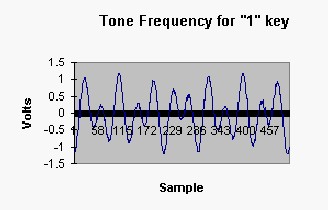
Figure (B)
Along
with these DTMF generator in our telephone
set provides a set of special purpose groups of tones, which is normally
not used in our keypad. These tones are identified as 'A', 'B', 'C', 'D'.
These frequencies have the same column frequency but uses row frequencies
given in the table in figure (A). These tones are used for communication
signaling.
The
frequency table is as follows:
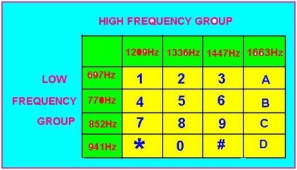
Figure (C)
Due to
its accuracy and uniqueness, these DTMF signals are used in controlling
systems using telephones. By using some DTMF generating IC�s (UM91214,
UM91214, etc) we can generate DTMF tones without depending on the
telephone set.
CIRCUIT DESCRIPTION:
This system is divided into two sections, 1:
Remote Section 2: Local Control Section.
REMOTE SECTION:
This unit consists of telephone
set which is present in the remote place. This may be your workspace
(office / school) phone or mobile phone or a phone in PCO. Signals are
sent through this telephone. The figure (E) shows the circuit diagram of
the DTMF encoder which resembles the telephone set. It uses DTMF encoder
integrated circuit, Chip UM 91214B
(click here to download datasheet). This IC produces DTMF
signals. It contains four row frequencies & three column frequencies. The
pins of IC 91214 B from 12 to 14 produces high frequency column group and
pins from 15 to 18 produces the low frequency row group. By pressing any
key in the keyboard corresponding DTMF signal is available in its output
pin at pin no.7. For producing the appropriate signals it is necessary
that a crystal oscillator of 3.58MHz is connected across its pins 3 & 4 so
that it makes a part of its internal oscillator.
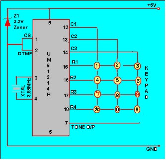
Figure (E).
Circuit diagram of the DTMF encoder
This encoder IC requires a voltage of 3V.
For that IC is wired around 4.5V battery. And 3V backup Vcc for this IC is
supplied by using 3.2v zener diode.
The row and column frequency of this IC is
as on the fig. "B". By pressing the number 5 in the key pad the output
tone is produced which is the resultant of addition of two frequencies, at
pin no. 13 & pin no.16 of the IC and respective tone which represents
number '5' in key pad is produced at pin no.7 of the IC . This signal is
sent to the local control system through telephone line via exchange.
LOCAL CONTROL
SECTION:
This is a
control unit through which you can control your appliances. This contains
one telephone line and a Local Control Section. The appliances to be
controlled must be connected to telephone line through control unit.
Control unit is kept with a sufficient backup.
Local Control Section consists of a DTMF decoder, 4-16 line
decoder/demultiplexer, D-flip-flops, and relay driver circuits. Before
going into detail of the circuit, we will take a brief description about
integrated circuits used in local control section.
MT 8870 DTMF
decoder:
IC
MT8870/KT3170 serves as DTMF decoder
(click here to download datasheet). This IC takes DTMF signal
coming via telephone line and converts that signal into respective BCD
number. It uses same oscillator frequency used in the remote section so
same crystal oscillator with frequency of 3.85M Hz is used in this IC.
Working of IC MT8870:
The MT-8870
is a full DTMF Receiver that integrates both band split filter and decoder
functions into a single 18-pin DIP. Its filter section uses switched
capacitor technology for both the high and low group filters and for dial
tone rejection. Its decoder uses digital counting techniques to detect and
decode all 16 DTMF tone pairs into a 4-bit code. External component count
is minimized by provision of an on-chip differential input amplifier,
clock generator, and latched tri-state interface bus. Minimal external
components required include a low-cost 3.579545 MHz crystal, a timing
resistor, and a timing capacitor. The MT-8870-02 can also inhibit the
decoding of fourth column digits.
MT-8870
operating functions include a band split filter that separates the high
and low tones of the received pair, and a digital decoder that verifies
both the frequency and duration of the received tones before passing the
resulting 4-bit code to the output bus.
The low and high group tones are separated
by applying the dual-tone signal to the inputs of two 6th order
switched capacitor band pass filters with bandwidths that correspond to
the bands enclosing the low and high group tones.
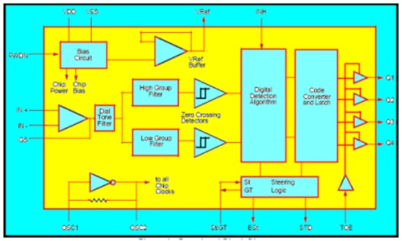
Figure (F).Block
diagram of IC MT8870
The
filter also incorporates notches at 350 and 440 Hz, providing excellent
dial tone rejection. Each filter output is followed by a single-order
switched capacitor section that smoothes the signals prior to limiting.
Signal limiting is performed by high gain comparators provided with
hysteresis to prevent detection of unwanted low-level signals and noise. The
MT-8870 decoder uses a digital counting technique to determine the
frequencies of the limited tones and to verify that they correspond to
standard DTMF frequencies. When the detector recognizes the simultaneous
presence of two valid tones (known as signal condition), it raises the
Early Steering flag (ESt). Any subsequent loss of signal condition will
cause ESt to fall. Before a decoded tone pair is registered, the receiver
checks for valid signal duration (referred to as character-
recognition-condition). This check is performed by an external RC time
constant driven by ESt. A short delay to allow the output latch to settle,
the delayed steering output flag (StD) goes high, signaling that a
received tone pair has been registered. The contents of the output latch
are made available on the 4-bit output bus by raising the three state
control input (OE) to logic high. Inhibit mode is enabled by a logic high
input to pin 5 (INH). It inhibits the detection of 1633 Hz.
The output code will remain the same as the
previous detected code. On the M- 8870 models, this pin is tied to ground
(logic low).
The input arrangement of the MT-8870
provides a differential input operational amplifier as well as a bias
source (VREF) to bias the inputs at mid-rail. Provision is made for
connection of a feedback resistor to the op-amp output (GS) for gain
adjustment.
The internal clock circuit is completed with
the addition of a standard 3.579545 MHz crystal.
The input arrangement of the MT-8870
provides a differential input operational amplifier as well as a bias
source (VREF) to bias the inputs at mid-rail. Provision is made for
connection of a feedback resistor to the op-amp output (GS) for gain
adjustment.
The internal clock circuit is
completed with the addition of a standard 3.579545 MHz crystal.

Figure (D). BLOCK DIAGRAM OF THE SYSTEM
Figure (D) shows the overall block diagram of "Device control using the
telephone" construction.
IC
NE 555 timer:
The NE555 is
an integrated circuit that capable of producing accurate timing pulses.
This IC is used as a multivibrater
(click here to download datasheet). By using this IC we can
construct two types of multivibrater, monostable and astable. The
monostable multivibrater produces a single pulse when a triggering pulse
is applied to its triggering input. The astable multivibrater produces a
train of pulses depending on the Resister-Capacitor combination wired
around it.
With a
monostable operation, the time delay is controlled by one external
resistor and one capacitor connected between Vcc-Discharge (R), and
Threshold-Ground (C). With an astable operation, the frequency and pulse
width are produced by two external resistors and one capacitor connected
between Vcc-Discharge (R), Discharge-Threshold (R), and Threshold-Ground
(C).
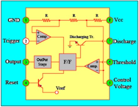
Figure J. IC
NE 555
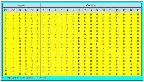
74154
4-16 line decoder/demultiplexer:
IC 74154 is a 4-16 line decoder,
it takes the 4 line BCD input and selects respective output one among the
16 output lines
(click here to download datasheet). It is active low output IC
so when any output line is selected it is indicated by active low signal,
rest of the output lines will remain active high. This 4-line-to-16-line
decoder utilizes TTL circuitry to decode four binary-coded inputs into one
of sixteen mutually exclusive outputs when both the strobe inputs, G1 and
G2, are low. The demultiplexing function is performed by using the 4 input
lines to address the output line, passing data from one of the strobe
inputs with the other strobe input low. When either strobe input is high,
all outputs are high. These demultiplexer are ideally suited for
implementing high-performance memory decoders.

Figure G. IC
74154 4-16 line decoder
All inputs
are buffered and input clamping diodes are provided to minimize
transmission-line effects and thereby simplify system design.
TRUTH TABLE:
74126
Tri - State Buffer:
This IC is a
tri state buffer contains four independent gates each of which performs a
non-inverting buffer function. The outputs have the 3-STATE feature
(click here to download datasheet). When control signal is at
high state, the outputs are nothing but the data present at its input
terminals. When control signal is at low state, the outputs are held at
high impedance state. So no output will be available at the output
terminal.
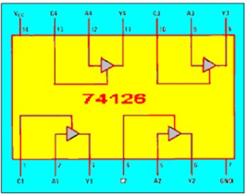
Figure H. IC
74126
IC
7474 D-flip-flop:
IC 7474 is a
conventional D-flip-flop IC. This IC consists of two D flip-flops. These
flip-flops are used to latch the data that present at its input terminal
(click here to download datasheet). Each flip-flop has one
data, one clock, one clear, one preset input terminals.
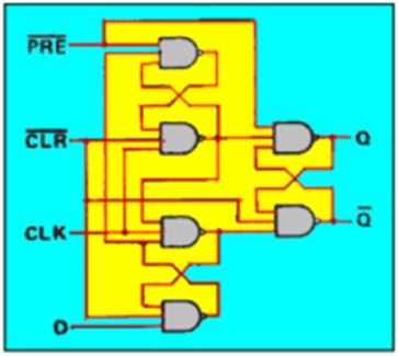
(Above figure
shows a single D-flip-flop)
IC
7447 BCD - seven segment decoder:
The DM74LS47
accepts four lines of BCD (8421) input data, generates their complements
internally and decodes the data with seven AND/OR gates having
open-collector outputs to drive indicator segments directly
(click here to download datasheet). Each segment output is
guaranteed to sink 24mA in the ON (LOW) state and withstand 15V in the OFF
(HIGH) state with a maximum leakage current of 250 mA. Auxiliary inputs
provided blanking, lamp test and cascadable zero-suppression functions.
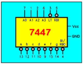
Figure I. IC 7447 BCD - seven segment decoder
WORKING
OF LOCAL CONTROL SECTION:
Local control
section contains a telephone interface circuit, ring detector circuit,
signal decoder circuit, device status check circuit, device controlling
circuit, device status feedback circuit.
1.
Telephone interface circuit:
When a signal
is sent from the remote telephone, the telephone interface circuit comes
to receive the signal. This circuit is directly connected to the telephone
line. This circuit consists of some passive components like resisters,
capacitors.
2.
Ring detector circuit:
This circuit
is useful to receive the telephone in the absence of the person. This
circuit identifies the ringing signal sent from the telephone exchange. On
getting the ringing signal this circuit connects the master unit to the
telephone line.
When some one calls another person through telephone by dialing second
persons number, on getting this number of the second person the system in
the telephone exchange sends a short duration ringing signal, this signal
is sent at 25-30 Hz pulse of 70-90 rms.
This AC
signal is bypassed by resister RE and capacitor CE and applied to the
optocoupler MCT2E. This optocoupler is 6 pin IC. This is made up of
internally built one Light Emitting Diode (LED) and a transistor. When the
internal LED glows, the light falls on the emitter-collector junction the
transistor. By this transistor is forward biased and the output is
obtained at the emitter of the transistor.
On applying
the signal to anode of the optocoupler, grounding the cathode, on the
positive cycle of the signal LED glows as a result +5volt output is
obtained at the emitter of the optocoupler at pin no 4.
The
ring detector circuit is built around a monostable multivibrater
constructed around timer IC 555.
When a
negative going pulse is applied to its triggering input at pin 2, the
output of the IC goes high. This output is available at pin 3 of this IC.
This will remain high for the time period designed by the RC combination.
Depending on values of resister RA and capacitor CA.
High on the
pin 3 of this timer IC biases the transistor T2 in the relay driver
circuit which in tern switches ON the relay. This relay puts a resistance
loop of 220Ω across the telephone line. By this resistance loop the line
voltage in the telephone line drops from 50v to 12v. This is same as
lifting the receiver of telephone handset (hook-off state).
Here this circuit is designed for a period of 60 seconds. This
period is calculated by the formula,
td = 1.1 RA
CA
After this
period the output of this IC goes low which intern switches OFF the
transistor T2. By varying the values of the RA and CA
the ON period of the monostable multivibrater is changed according to the
formula given above. In the relay driver circuit resister is used to
provide the necessary base current to the transistor so that it can bias
properly.
Now our circuit is ready to receive any coded signal of
the devices connected to the local control section from the remote control
section.

Fig J.
Circuit Diagram of Local Control Section.
3.
Signal Decoding Unit:
This is the main unit of this
system. This unit consists of a DTMF to BCD decoder IC MT 8870, 4 to 16
line decoder IC 74154 and hex inverter gate IC 7404
(click here to download datasheet). The working of all the
above IC's are mentioned here before.
The DTMF to
BCD decoder IC MT8870 takes a valid tone signal from the telephone line.
Then the tone signal is converted in to 4 bit BCD number output obtained
at pins from 11 to 14. This output is fed to the 4-16 line decoder
IC74154. This IC takes the BCD number and decodes. According to that BCD
number it selects the active low output line from 1 to 16 which is decimal
equivalent of the BCD number present at its input pins. Since the low
output of this IC the output is inverted to get logic high output. This
inversion is carried out by hex inverter IC 7404- built on TTL logic. This
IC inverts the data on its input terminal and gives inverted output.
4.
Number display unit:
This unit
displays the received device code from the telephone line dialed from
remote section. This unit consists of a BCD to seven segment decoder
IC7447 and a seven segment display.
A seven
segment display has seven LEDs connected in a sequence to give a regular
shape and a LED to display the dot for decimal point.
It has 10
pins. Out of this two pins are common for all LEDs and remaining are
another polarity terminals of the LED. When common anode seven segment
display is used, two common terminal pins are connected to +5v or logic
high state and another terminal are kept at logic low state. Then
respective LED glows.
Here common
anode seven segment display is used. Because of this here we need a BCD
to seven segment decoder which gives logic low output for the respective
BCD input. Therefore I used a TTL IC 7447.
The device selected from the
Remote Section for control purpose, its code is displayed in this seven
segment display.
Next we discuss about the device
control unit .This is an important unit in this project.
Device
control unit consist of device status check unit, device switching unit,
device status feedback unit, relay driver circuit and beep tone generator
unit.
Now we see
these units in detail.
5.
Device status check unit:
Before switching On/Off any device, we always have confusion about
its present status. If we are not sure about its status and if we false
switch the appliance, then this will lead to some problems like damaging
the device. Here we provide a facility that tells about present status of
the device.
The inverted
output of 4-16 line decoder and the output of respective flip-flop are fed
to the independent block of AND gate of IC 8- IC12 using IC 7408
(click here to download datasheet). If the device is already in
the ON state, then we will here a beep sound. The output of each AND gate
are connected to the beep tone generator unit by using a transistor. This
beep generator unit produces a short duration beep indicating than the
device is already in switched ON state.
If device is
in OFF state then no beep will be heard.
6.
Device switching unit:
This unit consists of a tri state buffer and a D flip flop.
After making confirmation of current status of the device to alter the
status of that device, you have to change the mode of the tri state buffer
by making the control input high. This is done by pressing the �#� key.
When this key is pressed the output of the 4-16 line decoder goes low.
This gives a triggering pulse to monostable multivibrater which is build
around the IC 6. This will keeps the output high for a 5seconds. Working
of the monostable multivibrater already discussed. In this time interval
the output of the tri state buffer will be the signal at its input
terminal.
So now the device code of the
respective device is again pressed whose status is to be altered.
The output of tri state buffer is
latched by using a D flip-flop. Here this D flip flop is used in the
toggle mode. For each positive going edge of the clock pulse will trigger
the flip flop.
After a period of 5 seconds the
output of the IC 6 goes low and puts the tri state buffer in the high
impedance state. Therefore to change the status of any other device is to
be done after the output of IC 6 goes low, again �#� key is pressed to
make the tri state buffer act as input �output state and the respective
code of the device is pressed.
6.
Device status feedback unit:
After changing the present status of the device confirm the
operation you did, here comes the unit which gives the feedback tone after
switching ON any device. This device status feedback unit uses a dual
input AND gate, the output of the flip flop and the tri state buffer are
to as the input. When the both inputs are high that indicates that device
is switched ON, then the output of the AND gate goes logic high state.
This output is fed to the beep generator unit through switching a
transistor. Until you press the key the feedback tone is heard
This feedback tone is heard only
when the device is switched ON. While switching OFF the device this tone
is not heard.
7.
Beep tone generator unit:
Beep tone
generator unit produces a beep tone of audible frequency. This unit is
constructed using a 555 timer chip. Here it is wired as an astable
multivibrater with a few external components like resister and capacitor
are required along with the timer 555 chip set.
This frequency comes in the audible range between 40Hz to 650Hz.
It should be less than 650Hz otherwise it will mix up with the DTMF tone.
When it is less than 650Hz the frequency which causes the false triggering
is filtered-off by the external structure of DTMF decoder IC MT8870.
8.
Power supply unit:
For the proper working of this local control section except the
local telephone set it needs a permanent back up which gives a 5V back up
continuously. This is achieved by using a 5V regulated power supply from a
voltage regulated IC 7805. This 5V source is connected to all ICs and
relays. This IC gets a backup from a 9V battery.
9.
Relay driver circuit:
To carry out
the switching of any appliances or devices we commonly use the relays.
Since the output of the D flip flop is normally +5V or it is the voltage
of logic high state. So we cannot use this output to run the device or
appliances. Therefore here we use relays which can handle a high voltage
of 230V or more, and a high current in the rate of 10Amps to energize the
electromagnetic coil of the relays +5V is sufficient. Here we use the
transistors to energize the relay coil. The output of the D flip-flop is
applied to the base of the transistor T5 � T15 via a resister. When the
base voltage of the transistor is above 0.7V the emitter-base (EB)
junction of the transistor forward biased as a result transistor goes to
saturation region it is nothing but the switching ON the transistor. This
intern switches on the relay. By this the device is switches ON. When the
output of D flip-flop goes low the base voltage drops below 0.7V as a
result the device also switches OFF.
ASSEMBLING
THE LOCAL CONTROL SECTION:
The whole local control section except local telephone set is assembled in
a single board, which is available in the market as common PCB. The whole
circuit except the devices is assembled in a single cabinet in which the
board gets fairly fitted along with power supply unit.
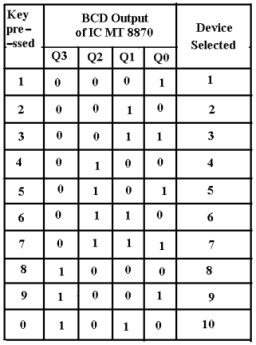
Table 2
A
parallel connection from the telephone line is taken and connected it to
telephone interfacing circuit using a DPDT switch. When you wish this
section is to be work then you switch ON the DPDT switch otherwise your
telephone is used for normal calling receiving purpose.
The connecters are provided to all
the relay switches so that the devices are connected easily. After
connecting, the devices, devices are given the number according to table
2.
Now power
supply is connected and devices are also connected so that the whole
section is ready for control device using a remote telephone set.
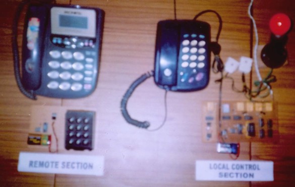
Prototype of
Device Control Using Telephone Project.
TESTING OF THE LOCAL
CONTROL SECTION:
Make sure that the installation of the
local control section is perfect; every thing is ready and local control
section is ready to receive signal from remote section. Now ON the DPDT
switch so that the telephone line is connected to telephone interfacing
unit.
Now make a
call to your telephone set using a remote telephone set or mobile phone.
The signal goes to telephone exchange and the exchange sends a ringing
signal to your set through phone line.
The ring
detector unit detects the ringing signal and makes the output of the IC5
to high state so that local control section of then connected to the
telephone for a time interval of 60 seconds.
Now we follow the steps to test the proper
switching of devices given below:
i).
Press the respective code of the device whose status is to be checked. The
dialed number of the device is displayed on seven segment display. If the
device is already switched ON then you will hear a short duration beep
tone from beep tone generator unit.
ii). Now
press the �#� button on the keypad and again press the device number, the
device number is displayed and now the device is switched OFF and you
won�t hear the feedback tone. Indicating that the device is switched OFF.
iii). Repeat
the above step (i) once again. In step (i) you won�t hear the beep tone
because the device is switched OFF during above step (ii). Repeat the step
(ii). Now you will hear the feedback tone because the device is switched
ON.
After 60 seconds the local control
unit will disconnected from the telephone line so that your money is
saved.
APPLICATIONS:
The main theme of
this project is to control the devices using telephone. By using the basic
idea of this project we can also construct many useful systems. I like to
share some of those here.
PBEX:
By using this
project we can construct the personally branched telephone exchange. In
many of the PBEX we seen in the offices require one operator to divert the
incoming calls to the respective internal telephone line. Here it does not
require any such operator to operate this exchange. The person from a
remote section is only to press the extension number to get connected to
the respective number. In this type of PBEX only 12 extensions can be
used.
Control
the light of advertising board:
In
advertising board or sign board used for display the company product
purpose at the road sides requires the focus light on the dusk time. To
control the light of this sign board a person is needed to switch on the
lights in the evening and switch off it in the morning time. By using this
system we can control the light from a control room or by the cell phone
of the marketing person.
Other Article/ Tutorials |